|
Phasor Noise |
- Where to find it:
- Add Procedural Layer / Procedural / Extension Pack / Gabor /
 NodeGraph / Right Mouse Click / Add Nodes / Procedural / Extension Pack / Gabor /
|
|
Phasor Noise is only available in Mari 4.7v2 or higher |
Phasor Noise is a powerful noise type, based on the Gabor Noise.
It allows a large number of looks to be achieved all with a single noise.
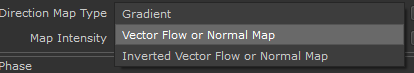
Since the noise is a directional noise, it can be fully oriented using gradients, normal maps and vector flow maps
Example of using Mari's Vector Paint Tool to paint flow direction
|
Video Tutorial |
|
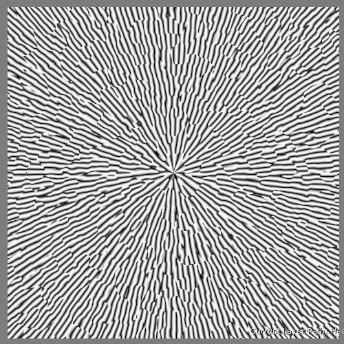
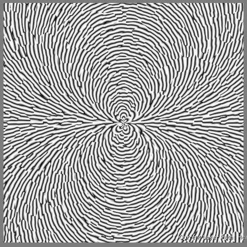
Samples |
Below you can see a small number of examples of the noise in action.
All examples use a single phasor noise node, applied as a displacement.
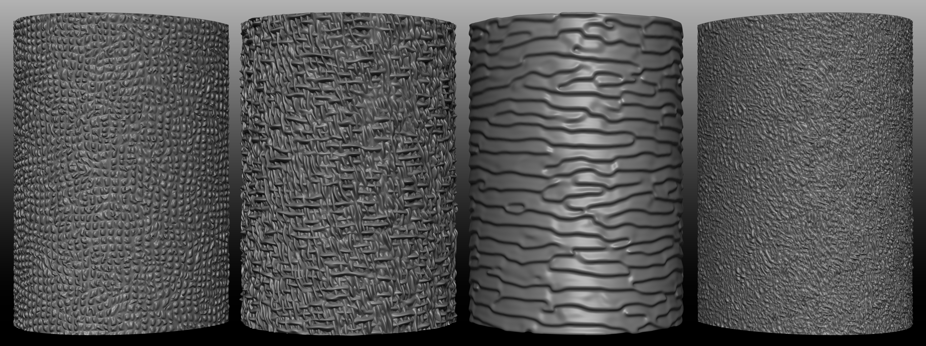
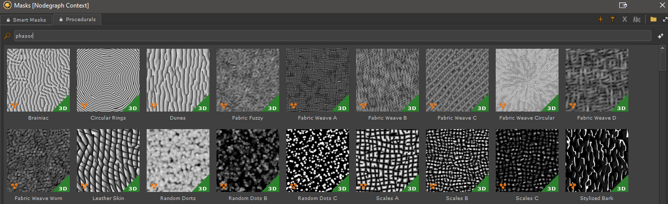
18 examples of Phasor Noise Presets have been added to the Mask Shelf, to provide some starting points. They can be found under the filter tag 'phasor'.
Phasor Noise Examples in the Mask Shelf, filtered by search term 'phasor'
|
Phasor Noise - High Level Overview |
This topic aims to give you a basic understanding of the concepts behind the noise, which will greatly help you to modify it to achieve certain
looks, without having to rely on trial-and-error.
While the Phasor Noise provides many options, which may seem daunting at first, its basic premise can be easily explained.
|
Kernel |
The noise works by drawing random dots or spheres on the surface of your mesh. The dots/spheres are called 'Kernel'.
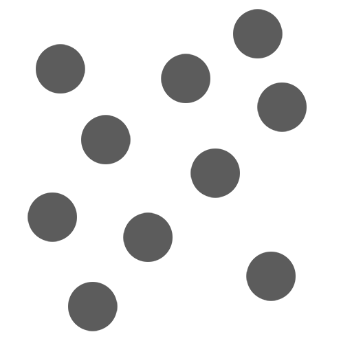
The Kernel Pulse Amount determines the density of dots/spheres.
The Kernel Frequency determines the size of the dots/spheres.
You can reveal each kernel 'dot' by reducing the Kernel Falloff:
The dots/spheres are blended together using a gaussian falloff. The hardness and 'turbulence' of the value
transitions is determined by the Kernel Falloff and Max Kernel Error Setting
|
Phase |
Within each dot/sphere a number of stripes are drawn. This is referred to as the Phase.
The number of stripes is determined by the Noise's main Frequency Setting
Additional options to control the Phase can be found under the Phase Settings Group
|
Kernel Dimensions |
It is important to understand the noise dimension, as this is one of the elements that can make it seem irregular and more difficult to control.
The kernel 'dots' can be flat 2d dots or 3d spheres. This is determined by the Dimension Setting of the Noise (XY vs XYZ).

The Noise is always generated in 3D Space. Setting the Dimensions to XY does not mean that it is evaluated
against the UVs of your model. It merely determines the way the phase is calculated.
The kernel is always initially generated as full 3D Spheres. If the Dimension is set to XY, the 3d sphere is then realigned and 'flattened' against the surface based
on its normals.
Both Dimensions have their uses and difficulties.
Kernel Dimension XYZ
The Kernel is a 3d Volume with the Phase (the stripes within a kernel) sitting in its center.
Depending on what angle you look at the 3d kernel (Dimension XYZ), the spacing between the stripes (frequency of the phase) might seemingly change
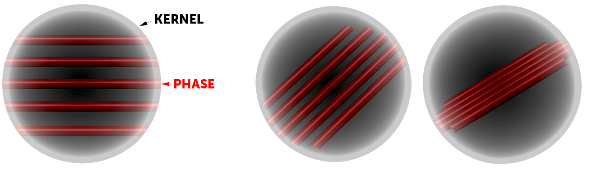
Additionally, having the Kernel in XYZ, also introduces complexities when trying to rotate or align the phase.
Instead of having a single angle value, you now have to consider 3 different axis rotation as shown in the illustration below.
The below illustration shows the complexities of having to rotate in
3d space vs having a single value when looking at the phase from the top
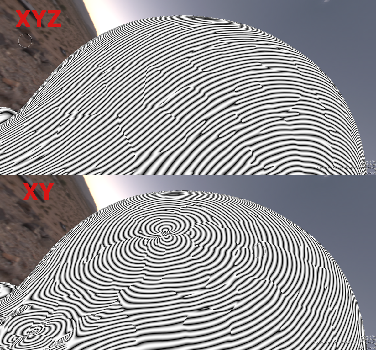
Kernel Dimension XY
By default the Noise will operate with a Kernel Dimension of XY only since it provides the most easy controls.
Depending on your model this might be enough.
In XY Dimensions the above sphere is 'flattened' to a disc and aligned to the normal of the model.
Depending on the normal orientation, this can seemingly introduce discontinuities between kernels which cannot be avoided.
Using the Direction Options as well as the Alignment options of the noise you can adjust the phase rotation to best suit your needs.
Comparison of a problematic surface area between dimensions XYZ and XY.
The differences become most apparent when rotating the phasor field via the direction group
|
Octaves |
Octaves determines the number of times the Noise is calculated. Each Octave can use incrementally other settings by
modifying e.g. Frequency for each octave.
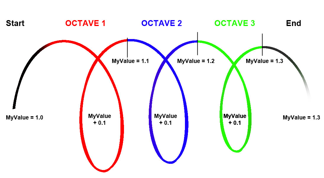
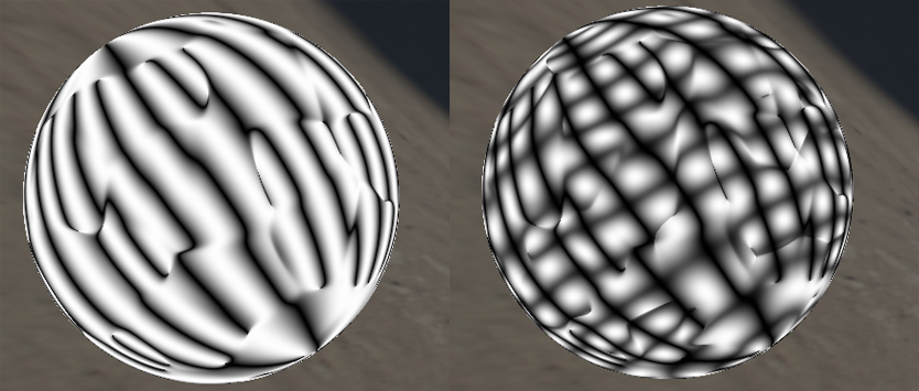
On the left we have the basic phasor noise ('Octave 1'). On the right we have the basic noise combined with a second octave.
The second octave has the same scale (frequency) and weight (opacity) as the main phasor field, but is rotated 90 degrees.
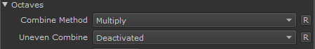
The Octave is blended using a 'Multiply' Blend Mode.
The Blend Mode of octaves doesn't have to be the same for each octave. Separate controls for evenly numbered and unevenly numbered
octaves are available
|
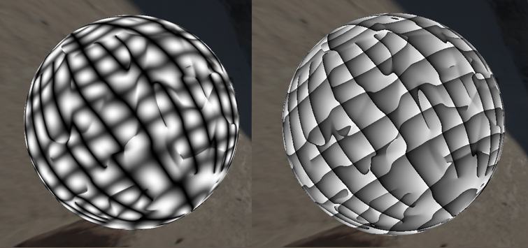
Profiles / Shaping |
The Profiles determine the look of the gradient of the Phase. Profiles can be different between the main Phasor Field (Octave 1) and
following octaves
Below you can see the same Phasor Noise with two different Profiles applied.
|
How can I paint the direction of the noise ? |
Due to the directional nature of the noise, the Phase (the stripes of the noise) can be aligned for each Kernel using Input Maps, therefore 'grooming' the noise.
The Noise supports grooming via Grayscale Gradients, Tangent Space Normal Maps as well as Vector Flow maps painted using Mari's Vector Tools.
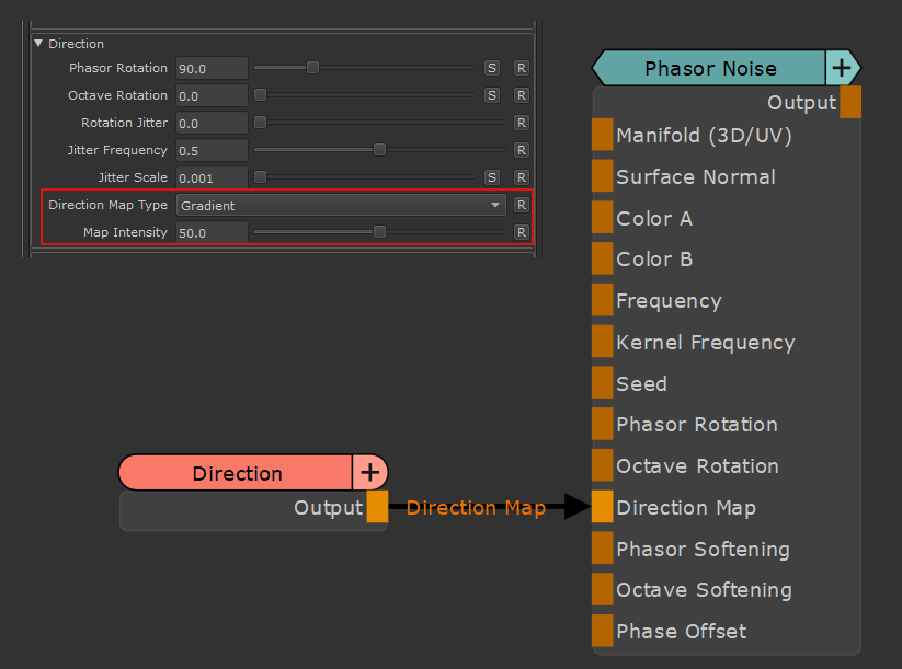
To groom the noise using an external input, attach the control to the DIrection Map Port of the Node and set the Type of Input in the Direction Group.
You can control the influence of the Map using the Map Intensity Slider and set a starting rotation via the Phasor Rotation and/or Octave Rotation Slider.
Gradients

In the example below we are using a simple Circular Gradient 2D Node to control the Direction
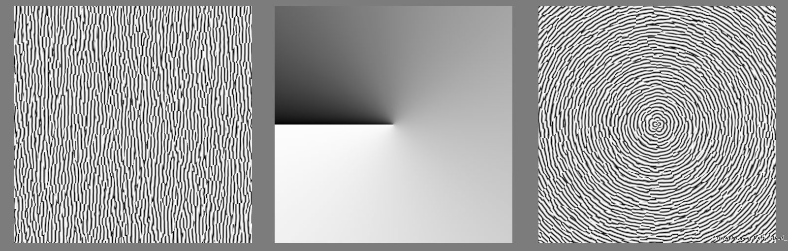
By changing the initial Phasor Rotation Slider to 90 degrees we get a slightly different look

Further modifications of the look by increasing the Map Intensity Slider to 100

Normal Maps

In the below example we are using a Tangent space Normal Map to control the direction
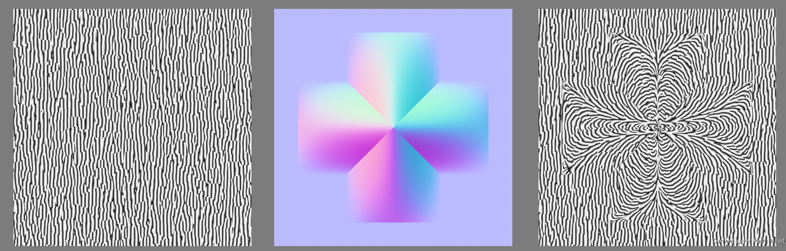
as with the Gradient you can control the intensity of the effect via the map intensity slider
and the starting rotation or 0-value (e.g. rotation when the normal map is blue, R=0.5,G=0.5,B=1.0) via the Phasor Rotation Slider
Depending on if you are using an OpenGL or DirectX Normal Map you can set the map type to your needs
Vector Flow Map
In the below example we are using a Vector Flow Map painted in Mari to control the direction
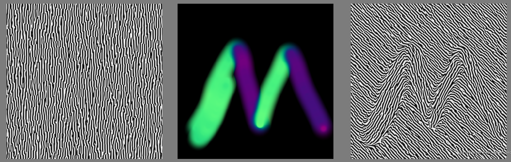
To use this workflow
- create a black 16bit or 32 bit paint node and attach it to the Direction Map Port of your Phasor Noise.
|
|
|
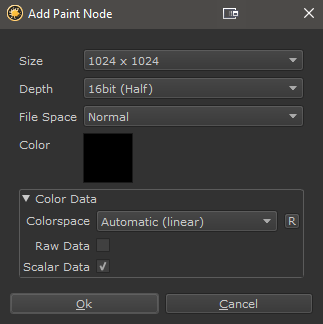
- Switch to the Vector Paint Tool in Mari's Toolbar
- Set the Painting Mode to Paint Flow Vectors

- Paint your direction.
As with the other map types, you can control the intensity of the effect via the map intensity slider
and the starting rotation or 0-value (e.g. rotation when the normal map is blue, R=0.5,G=0.5,B=1.0) via the Phasor Rotation Slider
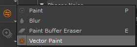
If you wish to invert the flow direction, you can switch the Map Type to Inverted.
|
Node Overview |
|
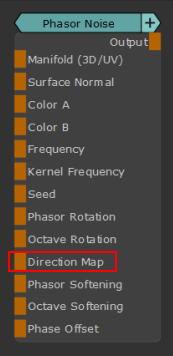
Node Ports |
- Manifold (3D/UV)
When this connection is mapped in the Nodegraph it will overwrite the coordinate system used by the Node.
By default, if the 3D Coordinates Handle is unmapped the Node will use your Objects Positional Data.
If the Manifold Port is mapped the Attributes in the Transform Tab of the Node are overwritten
- Surface Normal
Overwrites the Surface Normal used to calculate the Phasor Noise.
If the Aligned Direction slider in the Direction Group is set to 1.0, this port is no longer evaluated.
- Color A
Overwrites the Color A Attribute in the Color Group
- Color A
Overwrites the Color B Attribute in the Color Group
- Frequency
Controls the Frequency of the Phase.
Overwrites the Frequency Attribute in the Main Group
- Kernel Frequency
Controls the Frequency of the Kernel.
Overwrites the Frequency Attribute in the Kernel Group
- Seed
Controls the Seed of the Phasor Noise.
Overwrites the Seed Attribute in the Main Group
- Phasor Rotation
Sets the initial Rotation of the Phasor Field.
This overwrites the Phasor Rotation in the Direction Group.
The Phasor Rotation can be set separately in X, Y an Z by using different values
in the Red, Green and Blue Channel of the Input.
- Octave Rotation
Sets the initial Rotation of the Octaves.
This overwrites the Octave Rotation in the Direction Group.
The Octave Rotation can be set separately in X, Y an Z by using different values
in the Red, Green and Blue Channel of the Input.
- Direction Map
Allows you to control directions of the Phasor field via a gradient, normal map
or Vector Flow Map.This can be set in the Direction Group.
|
|
|
- Phasor Softening
Allows you to control the Phasor Field Softening.
This overwrites the Phasor Softening in the Phasor Profile Group.
- Octave Softening
Allows you to control the Octave Softening.
This overwrites the Octave Softening in the Octave Profile Group.
This will not have any effect unless you deactivate the 'Link to Phasor Profile'
setting in the Octave Profile Group
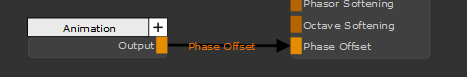
- Phase Offset
The Phase Offset offsets the 'Stripes' along the surface. The Phase Offset is divided by the Offset Divison Slider
to get a stronger or weaker offset.
In the below example an animation node is connected to the Phase Offset and the Offset Division is raised slightly to control the speed
of the animation
|
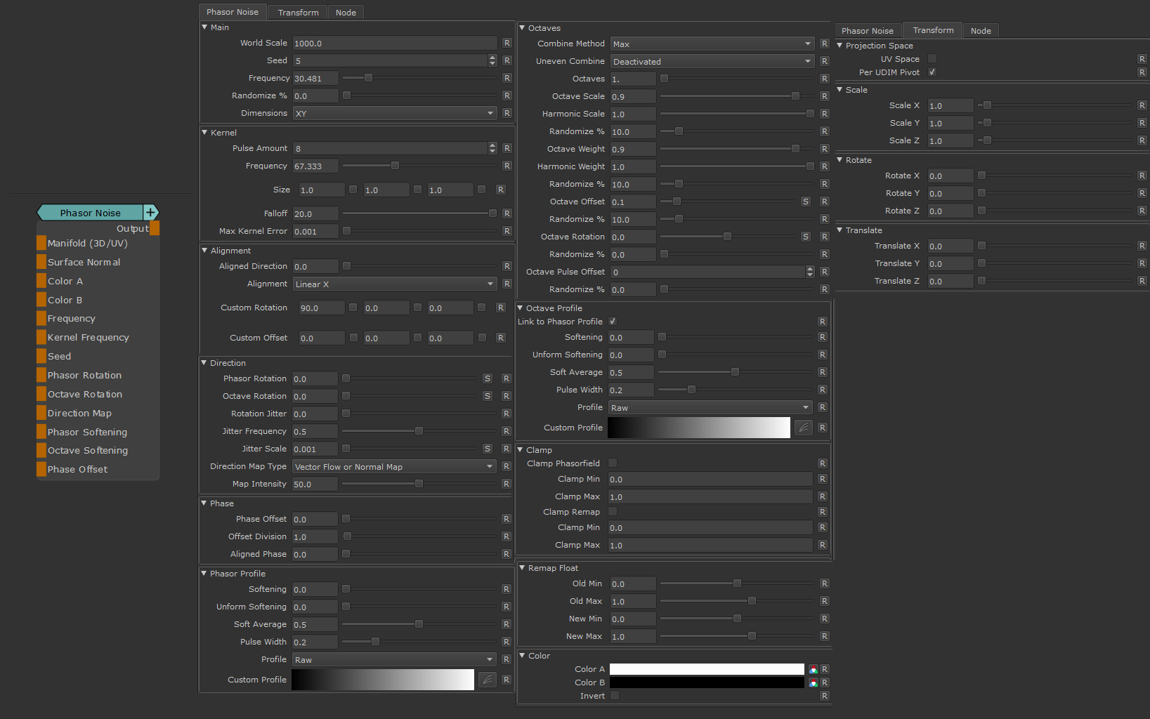
Node Properties |
MAIN TAB
|
Main |
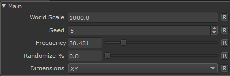
- World Scale
Linearly increase the scale of the Phasor Noise.
Larger Values mean a larger overall result while the general look remains unchanged
- Seed
Changing the Seed will generate variations of the Phasor Noise with the same look.
The attribute can be overwritten by a Node Port connection.
|
|
If the Seed is too large (e.g. >9999) you might get unexpected results |
- Frequency
Adjusts the density of the Phase.
The Phase is the number of stripes within each Kernel Dot.
A higher frequency means a larger number of stripes.
The attribute can be overwritten by a Node Port Connection.
- Randomize %
Randomizes the Frequency (e.g. the number of stripes) per Kernel Dot.
The maximum Randomization value to add to the Frequency is
(Frequency / 100) * Randomize%
- Dimensions
Determines if each Kernel should be generated as a 3D Sphere (XYZ) or a 2D Disc (XY).
While the initial calculation always happens as a 3D Sphere, when XY is chosen, the result
gets flattened against the normal of the Object.
The default setting is XY, since it provides the most intuitive Direction Setting Options.
\n\nThe differences between the two modes become apparent when increasing the Phasor Rotation via the
Direction Group
|
|
Refer to the general explanation of the Dimension Settings for more details |
|
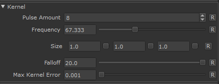
Kernel |
|
|
Refer to the general explanation of the Kernel Settings for more details |
- Pulse Amount
The Kernel Pulse Amount determines the density of dots/spheres.
|
|
Keep the Pulse Amount as low as possible since higher values will impact viewport FPS |
- Frequency
The Kernel Frequency determines the size of the dots/spheres.
A higher frequency means more and smaller cells over the same surface area.
The Attribute can be overwritten by a Node Port connection
- Size
A per-axis multiplier for the size of the kernel dots/spheres.
- Falloff
The Kernel Falloff determines the size of the Gaussian Falloff of each cell.
Smaller Values will lead to gaps inbetween cells that can only be filled by increasing the Pulse Amount.
Having small Values will allow you to see each cell which can be helpful to debug.
- Max Kernel Error
Set how much error and discontinuity is allowable in sampling the kernel cells.
While increasing the value fills in discontinuities using a Gaussian falloff it can also introduce new
discontinuities along the kernel cell grid.
|
Alignment |
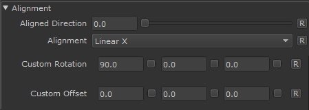
The Alignment Group allows you to specify an alignment of the phasor features in one axis.along a normal axis
In addition you can define a custom normal orientation.
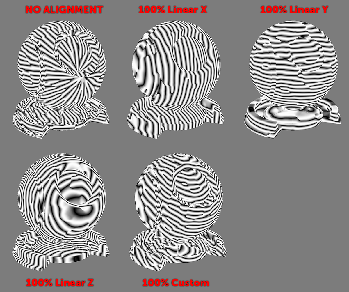
Examples of different pre-alignments
- Aligned Direction
Specifies how much of the pre-defined Alignment (dropdown below) is mixed into the calculation.
|
|
If 100% Aligned Direction is mixed in, the Surface Normal Port of the Node is no longer contributing to the calculation |
- Alignment
- Linear X / Y / Z
Aligns the Features of the Phasor Noise along a specific world normal axis
Please note you are still able to rotate the features via the Direction Group
- Custom
Aligns the Features in the normal axis defined via the Custom Rotation and Custom Offset
values below the dropdown
Please note you are still able to rotate the features via the Direction Group
- Custom Rotation
Specify a custom Normal Rotation for the Phasor Noise.
This is similar to attaching a Surface Normal Node with custom rotation to the Surface Normal Port
of the Phasor Node.
- Custom Offset
Specify a custom Normal Offset for the Phasor Noise.
This is similar to attaching a Surface Normal Node with custom offset to the Surface Normal Port
of the Phasor Node.
|
Direction |
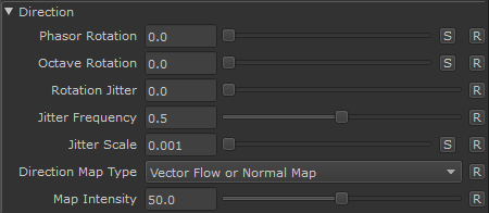
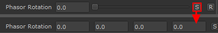
- Phasor Rotation
Sets the rotation of the phasor field relativ to the Normal.
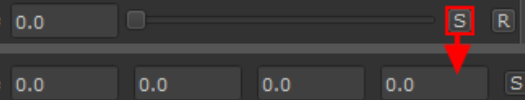
By clicking on the 'S' Button you can set the rotation for each axis (X, Y , Z) separately, which is important especially when using
Dimensions XYZ to configure the different axis rotations
If you are having trouble getting a correct rotation that fits your model, consider experimenting with the
This setting can be overwritten by a connection to a Node Port.
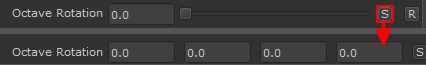
- Octave Rotation
Sets the initial rotation of the first additional octave of the phasor field.
Octaves can be activated in the Octave Group.
By clicking on the 'S' Button you can set the rotation for each axis sX, Y, Z) separately, which is important especially when using
Dimensions XYZ to configure the different axis rotations
If you are having trouble getting a correct rotation that fits your model, consider experimenting with the
This setting can be overwritten by a connection to a Node Port.
- Rotation Jitter
Adds a random rotation Jittering based on a Value3D noise
- Jitter Frequency
Determines the Frequency of the Value3D noise used to apply Rotation Jittering
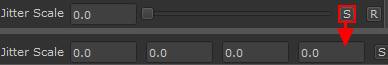
- Jitter Scale
A scale multiplier per axis on the Value3D Noise used to apply Rotation Jittering
Pressing the "S" Button will allow you to set separate values for X Y and Z
- Direction Map Type
|
|
|
Determines what kind of data is used to edit the direction, via the Direction Map Port of the Node
- Direction Map Intensity
Controls the intensity of the Direction Map attached to the Direction Map Port of the Node.
50 (default) is 1:1 the original value, 100 is doubled intensity
|
Phase |
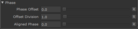
The Phase of the Noise in simple terms refers to the Stripes within each Kernel Dot/Sphere.
The Frequency of Stripes is controlled by the Frequency in the Main Group.
The Phase Group houses additional options
- Phase Offset
The Phase Offset offsets the 'Stripes' along the surface. The Phase Offset is divided by the Offset Divison Slider
to get a stronger or weaker offset.
This setting can also be controlled via an attachment to a Node Port.
In the below example an animation node is connected to the Phase Offset and the Offset Division is raised slightly to control the speed
of the animation
- Offset Division
A Divisor on the Phase Offset to control the strength of the offset
- Aligned Phase
The Phase Alignment will try to align each Pulses Phase with the other Pulses.
Each Pulse is filled with a number of Stripes (the phase) as defined by the main Frequency.
By default each pulse has an offset, meaning that the stripes between two pulses are not perfectly
aligned on the same plane.
Phase alignment will try and rectify this, meaning that stripes are more continuous across cells.
If you have varying rotations in between pulses (e.g. Rotation Jitter), Phase Alignment may not help.
|
Phasor Profile |
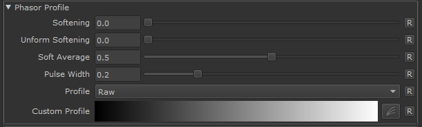
The Phasor Profile Group houses options to shape the gradient of the Phasor Field.
- Softening
Mixes in the value set via the Soft Average Slider using the method defined via the
Uniform Softening Slider.
This attribute can be overwritten via a node port connection.
- Uniform Softening
Determines if Softening is applied only to areas of high turbulence (0.0) or uniformly across
the phasor field (1.0)
- Soft Average
The value to mix in when Softening the Phasor field.
- Pulse Width
If the Profile Dropdown is set to Pulse or Pulse Centered, the slider gives you addtional
control over the look
- Profile
The Profile Dropdown allows you to choose from several Phasor Shaping Presets
or define your own using a Custom profile
Examples of different Shaping Presets applied to the same phasor field

- Custom Profile
If the Profile Dropdown is set to Custom Profile, you can define a custom shaping curve here.
|
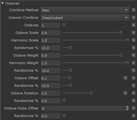
Octaves |
|
|
Refer to the general explanation of the Octaves for additional details, to better understand the concept behind octaves |
- Combine Method
Defines the Blend Mode used to combine Octaves from 2 on wards with the main Phasor Field (which is considered Octave 1)
If the Uneven Combine Dropdown is set to anything other than 'Deactivated', the 'Combine Method' determines the Blend Mode
used to combine even-numbered Octaves"
- Uneven Combine (Method)
If set to anything other than 'Deactivated', the Uneven Combine chooses the Blend Mode used to combine uneven-numbered (3.5.7 etc.)
Octaves with the main phasor field.
In this case the above Combine Method Dropdown determines the Blend Moe for even numbered octaves (2,4,6 etc.).
- Octaves
The Number of Phasor Field Loops to run the calculation with. Each Loop generates a unique Phasor Field based on the main Phasor
Field Settings and the per-octave modifiers defined in the Octaves Group.
Each Octave is combined with the previous calculations using the Blend Modes chosen in the Combine Method or Combine Method and Uneven Combine dropdown.
The default value is 1, which will in essence (confusingly so) not calculate any octaves but only show the base phasor field.
|
|
Increasing the number of Octaves linearly affects performance since it reruns the full phasor field calculation for each octave |
- Octave Scale
Determines the Scale Subtraction each Octave should have. Scale factors are incremental from the previous octave scale
- Harmonic Scale
Determines the way Octave Scale should be applied.
At Harmonic Scale of 0.0, each octave scale is incremental from the previous scale, meaning that e.g. for an octave scale
of 0.9, the first Octave is scaled down 10 Percent from the Main Noise Scale, the second octave then scaled down a further
10 percent from the first Octave Scale.
At Harmonic Scale of 1.0, each octave scale factor is weighted against the octave number to prevent octave scales to get
really small. Harmonic Scale mixes in a lower scale factor for high octaves, to keep them at a visible size
- Randomize % (Scale)
Mixes in a randomized scale for each Octave
- Octave Weight
Determines the Weight Subtraction each Octave should have. Weight factors are incremental from the previous octave weight.
- Harmonic Weight
Determines the way Octave Weights should be applied.
At Harmonic Weight of 0.0, each octave weight is incremental from the previous weight, meaning that e.g. for an octave weight
of 0.9, the first Octaves opacity is lowered down 10 Percent, the second octave then lowered down a further 10 percent from
the first Octave Weight.
At Harmonic Weight of 1.0, each octave weight factor is weighted against the octave number to prevent octave weights to get
really small. Harmonic Weight mixes in a higher weight factor for high octaves, to keep them visible
- Randomize % (Weight)
Mixes in a randomized weight for each Octave.
- Octave Offset
Determines the Offset each Octave should have. Offsets are incremental from the previous octave offset.
Offsets can be configured per Axis by pressing the 'S' Button, which is especially important if the global
Dimensions of the Noise are set to XYZ.
- Randomize % (Offset)
Mixes in a randomized offset for each Octave
- Octave Rotation
Determines the Rotation each Octave should have.
Rotation Values are incremental from the previous octave Rotation.
The starting Rotation of the first Octave can be set in the Direction Group.
Rotation Values can be configured per Axis by pressing the 'S' Button, which is especially important if the global
Dimensions of the Noise are set to XYZ.
- Randomize % (Rotation)
Mixes in a randomized rotation for each Octave
- Octave Pulse Offset
An offset value per Octave for the Pulse Amount set in the Kernel Group.
You can use that to lower or raise the number of pulses for each octave.
Pulse Offsets are incremental, meaning each Pule Amount for each Octave is based on the
Pulse Amount of the previous Octave.
Pulse Amounts can affect the performance of the node, therefore keep an eye on the total number
of pulses and keep them as low as possible.
|
|
Keep the total Pulse Amount as low as possible since higher values will impact viewport FPS |
- Randomize % (Octave Pulse Offset)
Mixes in a random Number of Pulses per Octave
|
Octave Profile |
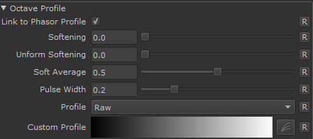
The Octave Profile Group houses options to shape the gradient of the Phasor Field generated for Octaves.
It can be either linked to the main Phasor Profile or be separate from it.
- Link to Phasor Profile
If on, all the settings in this group will be ignored and the Phasor Profile
will be used for the Octaves as well
- Softening
Mixes in the value set via the Soft Average Slider using the method defined via the
Uniform Softening Slider.
This attribute can be overwritten via a node port connection.
- Uniform Softening
Determines if Softening is applied only to areas of high turbulence (0.0) or uniformly across
the phasor field (1.0)
- Soft Average
The value to mix in when Softening the Phasor field.
- Pulse Width
If the Profile Dropdown is set to Pulse or Pulse Centered, the slider gives you addtional
control over the look
- Profile
The Profile Dropdown allows you to choose from several Phasor Shaping Presets
or define your own using a Custom profile
Examples of different Shaping Presets applied to the same phasor field
- Custom Profile
If the Profile Dropdown is set to Custom Profile, you can define a custom shaping curve here.
|
Clamp |
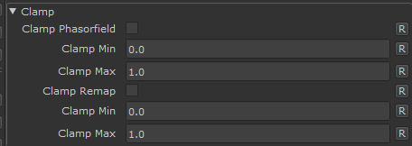
The Clamp Group contains all Clamping options of the Phasor Noise.
There are two Clamping Options available that sit at different positions in the computation
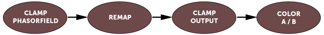
- Clamp Phasorfield
Determines if the direct computational output of the Phasor Noise is clamped.
Clamping happens before the remapping stage of the node.
- Clamp Min / Max
The minimum and maximum value to clamp the Phasorfield to
- Clamp Remap
Determines if the direct computational output of the Remapping is clamped.
Clamping happens after remapping and before application of the Colors A and B.
- Clamp Min / Max
The minimum and maximum value to clamp the Phasorfield to
|
Remap |
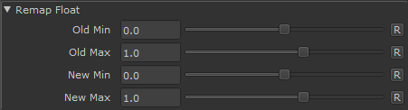
The Remapping Options allow you to remap the values coming from the Phasorfield computation.
The remapping is performed after the clamping of the Phasorfield (if turned on)
- Old Min / Max
Sets the original Value range
- New Min / Max
Sets the new Value Range.
E.g. and OldMin Value of 0 and a NewMin Value of 0.5 means that any value of 0 from the
Phasor Field will become 0.5
|
Color |
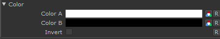
The Color Stage is the last part of the Computation, after all clamping and remmapping
- Color A/B
The background and foreground color of the Noise
These attributes can be overwritten via Node Port Connections
- Reverse
Reverses Color A and B
TRANSFORM TAB
- UV Space
By default this procedural is generated in 3D World Space.
By turning on UV Space the procedural is generated based on your UVs, resulting in seams between UV tiles/UDIM & shells.
Utilizing Transform Controls such as Scale (see below) you can apply a non-uniform transform to the procedural
to make use of specific UV layouts
- Per UDIM Pivot
Affects the transformation pivot for UV Transforms when in UV Space
With PerUDIMPivot on all transformation will be performed with a pivot at the centre of each UDIM.
With PerUDIMPivot off, transformations for all UDIMs share one common pivot at the base of UDIM 1001.
This will ensure seamless textures across UDIMs when your UV Shell is scaled up and covering multiple UDIMs.
without a cut inbetween.
UV Transformations applied to multiple UDIMs with perUDIM Pivot On (left) and off (right).

- Scale X / Y / Z
Will apply a scale along X,Y or Z to your noise. This is useful for creating patterns like woodgrain, drips etc.
When UV Space is turned on Scale Z is ignored.
- Rotate X / Y / Z
Will apply a rotation in X,Y or Z to your noise. When UV Space is turned on Rotate X & Rotate Y are ignored
and rotation is done around the center of each UV Tile/UDIM using Rotate Z.
- Translate X / Y / Z
Will apply an offset in X,Y or Z to your noise. When UV Space is turned on Translate Z is ignored.