|
Gabor Noise by Miguel A Santiago Jr. & Jens Kafitz |
- Where to find it:
- Add Procedural Layer / Procedural / Extension Pack / Gabor /
 NodeGraph / Right Mouse Click / Add Nodes / Procedural / Extension Pack / Gabor /
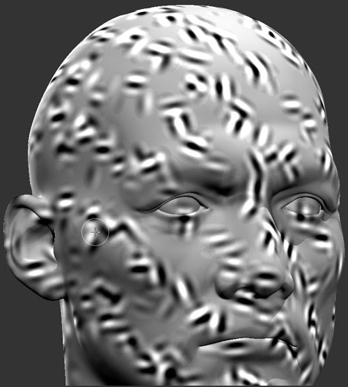
Gabor Noise is a procedural noise with the distinction that you can paint in the direction of noise features.
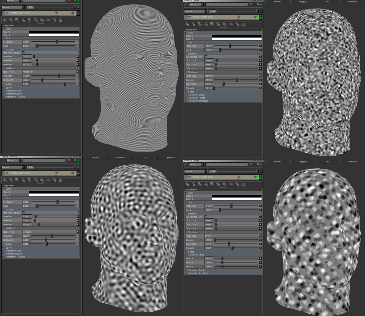
Gabor Noise is created by distributing round/oval cells in space. These cells can be oriented to have a direction.
By using Mari's Vector Tools these directions can be painted.
Step by Step:
1. Fill a new layer "MyPaint" with black or white and place it under the Paintable Gabor Noise
This represents your starting point - a constant direction of either x=0 / y=0 / z=0 (black)
or x=1 / y=1 / z=1 (white).
|
|
Use another fractal under the 'Paintable Gabor Noise' Layer for some interesting effects. |
2. In Paintable Gabor Noise tick on 'Use Painted Flow' under the Direction Group

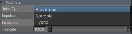
3. For more noticeable directionality switch 'Noise Type' to 'Anisotropic under the Modifiers Group
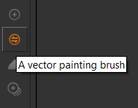
4. In the tools switch to the 'Vector Paint Brush'
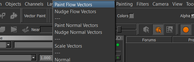
5. Under 'Painting Mode' a variety of Vector related options are available. 'Paint Flow Vectors' is usually fine.
6. On Layer 'MyPaint' start painting. You will see the Gabor cells orienting themselves along the direction of your brush stroke
|
|
Tip: Using 'Custom Object Normal' Node as a starting point Create a 'Custom Object Normal' Node under the Gabor Noise for a good starting point. With the 'Gabor Noise' hidden turn on 'Vector Inspection Grid' to get a preview of your vector direction then start painting. Switch on the 'Paintable Gabor Noise' to verify.
|
Due to the expensive nature of the node, the node has been marked in red
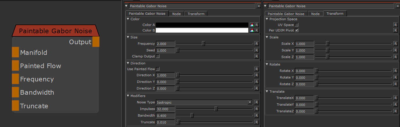
MAIN TAB
- Color A/B
The two colors that make up the final look of the procedural
- Frequency
Size of fractal features on your model
- Seed
A random start value for your fractal.
Changing the seed changes the overall look of your fractal while the general feature look stays the same, allowing for quick variation with a general look theme.
- Clamp Output
Clamps the noise calculation to a 0-1 range.
Color A/B are applied after the Clamping, so you can still set values above 1 if you choose to
however by clamping the Noise calculation the color mixing between the two colors works more
reliably. In general this should be left on.
- Use Painted Flow
With Use Painted Flow turned on, cell direction X,Y and Z is evaluated based on R,G and B Values from the combined result of all layers underneath the Paintable Gabor Noise Node.
- Direction X / Y / Z
Determines the direction of all Gabor cells in world space allowing you to give the Gabor Noise a directionality
- Noise Type
Gabor Noise works by distributing cells over your model. The Noise Type describes what Algorithm is used to determine orientation of cells.
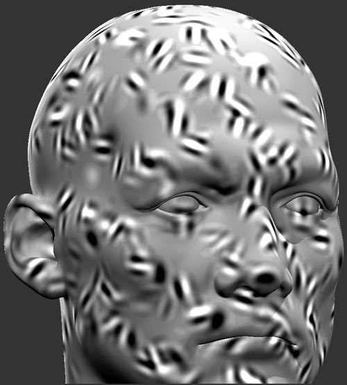
- Anisotropic
Cell Roration is determined based on directional settings from 'Direction' Group
Gabor with few impulses and 'Anisotropic' Setting
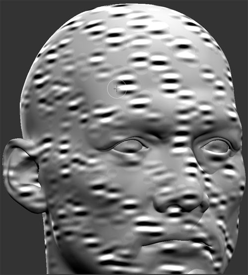
- Isotropic
Cells have a random starting rotation. Interior feature orientation of each cell is determined based on directional settings from 'Direction' Group
Gabor with few impulses and 'Isotropic' Setting
- Hybrid
Hybrid is a combination of Anisotropic and Isotropic.
Gabor with few impulses and 'Hybrid Setting
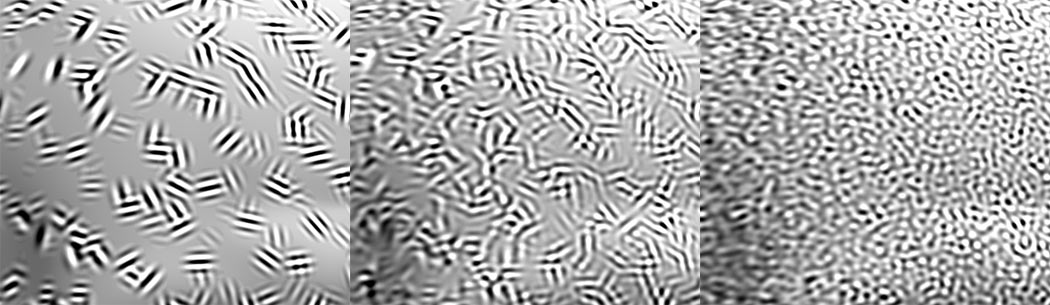
- Impulses
Impulses determines the number of Gabor Cells the fractal is made of
Gabor with low number impulses, medium number impulses and high number of impulses
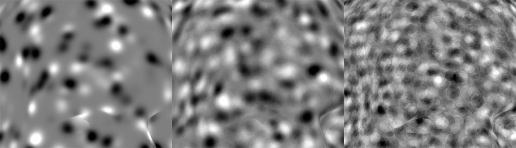
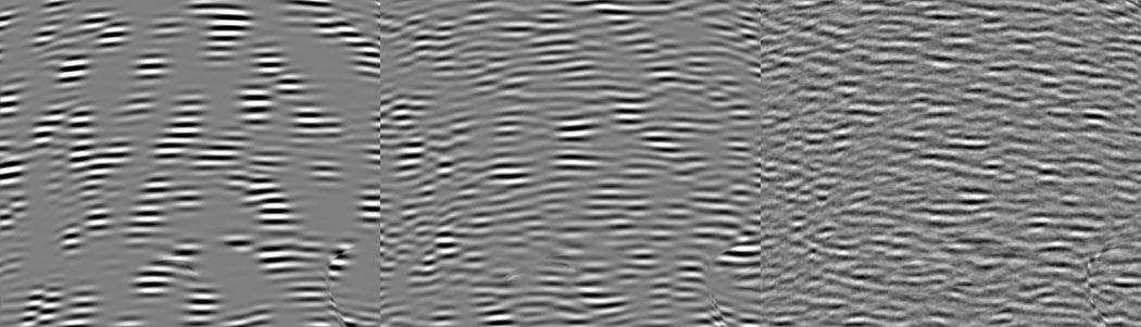
- Bandwidth
Bandwidth is in many ways similar to frequency - it changes the scale of features.
But while frequency just scales the complete result of the fractal, bandwidth scales the signals that make up the fractal individually
giving different results.
Gabor with low , mid and high bandwith
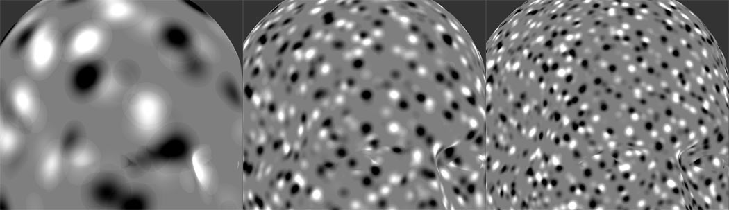
- Truncate
Limits the signal used for placing each gabor cell. Lower values result in more spare less overlapping distribution,
higher values in denser, overlapping cells
Gabor with low , mid and high Truncate Settings
Gabor with low , mid and high Truncate Settings with an additional directional component.
TRANSFORM TAB
- UV Space
By default this procedural is generated in 3D World Space. This results in a seamless noise across UV seams.
By turning on UV Space the procedural is generated based on your UVs, resulting in seams between UV tiles/UDIM & shells.
Utilizing Transform Controls such as Scale (see below) you can apply a non-uniform transform to the procedural
to make use of specific UV layouts
- Per UDIM Pivot
Affects the transformation pivot for UV Transforms when in UV Space
With PerUDIMPivot on all transformation will be performed with a pivot at the centre of each UDIM.
With PerUDIMPivot off, transformations for all UDIMs share one common pivot at the base of UDIM 1001.
This will ensure seamless textures across UDIMs when your UV Shell is scaled up and covering multiple UDIMs.
without a cut inbetween.
UV Transformations applied to multiple UDIMs with perUDIM Pivot On (left) and off (right).

- Scale X / Y / Z
Will apply a scale along X,Y or Z to your noise. This is useful for creating patterns like woodgrain, drips etc.
When UV Space is turned on Scale Z is ignored.
- Rotate X / Y / Z
Will apply a rotation in X,Y or Z to your noise. When UV Space is turned on Rotate X & Rotate Y are ignored
and rotation is done around the center of each UV Tile/UDIM using Rotate Z.
- Translate X / Y / Z
Will apply an offset in X,Y or Z to your noise. When UV Space is turned on Translate Z is ignored.