|
Cylindrical Projection |
- Where to find it:
- Add Procedural Layer / Procedural / Extension Pack / Generators
 NodeGraph / Right Mouse Click / Add Nodes / Procedurals / Extension Pack / Generators
Cylindrical Projection will project your image using cylindrical texture coordinates to avoid seams and ugly blending
on objects such as wheels, trees, barrels etc.
|
Positioning using Locators |
For easiest positioning turn on the 'Debug Pattern' Checkbox under the Texture Map Group of the Cylindrical Projection Node
- Select the Cylindrical Projection Node or Layer
- Activate the 'Transform Object' Tool in the Mari Toolbar.
This will trigger Extension Pack's Dynamic Locator System
- From the appearing dialog, choose what you want to modify.
Usually 'ALL' is what you want, in order to modify the Position and the Rotation
simultaneously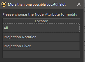
- Move the Locator to the appropriate position
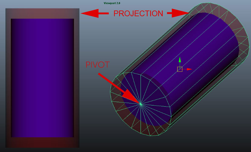
The position of this locator marks the pivot of the projection which is always located at the
'cap' center of the cylindrical projection
Cylinder Pivot is defining the center point of the 'cap' of your projection:
- Rotate the Projection into place. If you feel like the cylinder projection is facing the wrong direction, tick/untick the Mirror option.
Once you are happy with the general orientation you can use the Extra Attributes (Pivot Rotation) to make very precise adjustments
The aligned projection
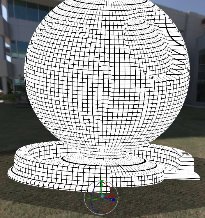
- Use the 'Length' Attribute to scale the Projection to a length, where the debug squares are uniform
- Turn off the Debug Pattern Option and plug in the map you want to project via the Main Tab
- By holding down CTRL you can snap rotations in increments. The Increments can be set in the Toolbar Stepping Angle Spinbox
- You can align a Locator to your view by pressing Align to View in the Toolbar
- You can adjust the size of the Locator by modifying the Locator Size Spinbox in the Toolbar
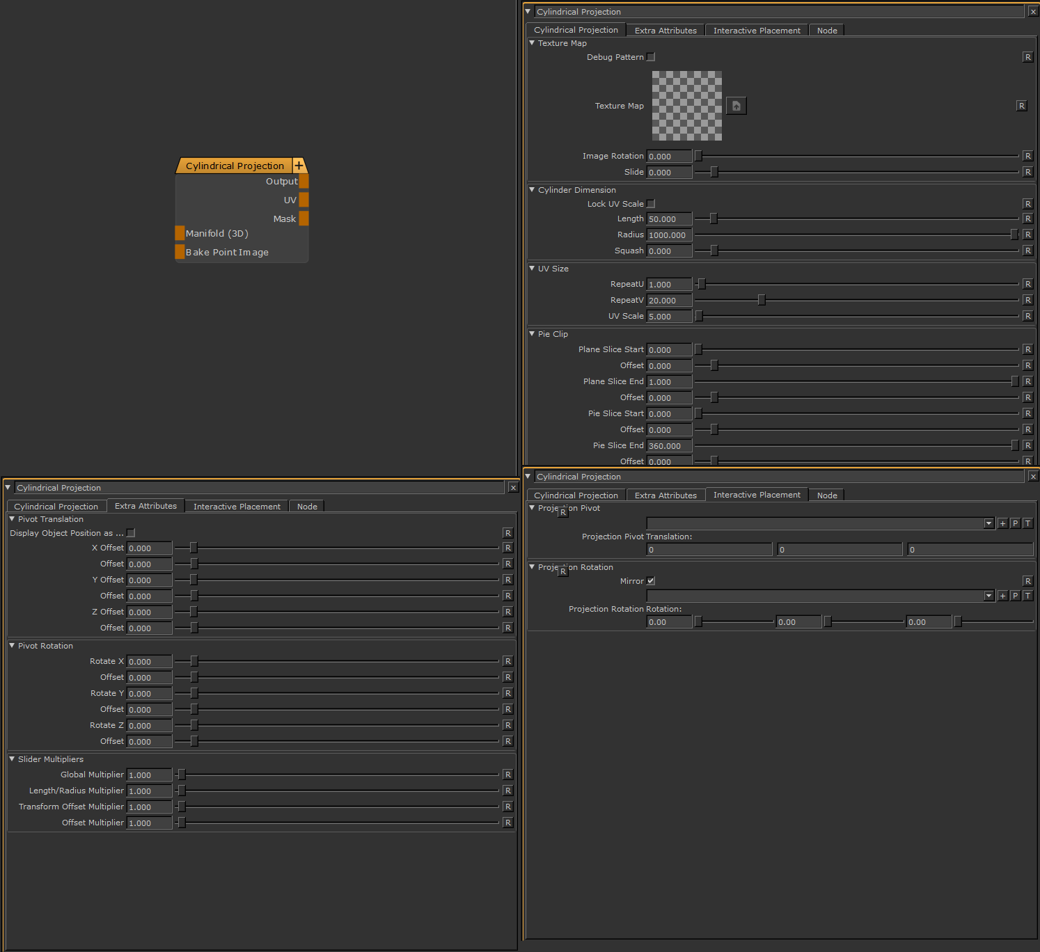
- Output
The Default Output
- UV
Outputs cylindrical UV Coordinates
- Mask
Outputs a black and white mask from your projection with Pie Mapping etc. applied
- Manifold 3D
IWhen mapped the world space position the node uses to calculate the projection is supplied by the port.
This can be used for example to apply warping to the projection using Manifold Nodes
- Bake Point Image
![]()
The Bake Point Image Port allows you to feed data into the Node from upstream nodes that have been baked via a bake point into the Node.
When the node is evaluated, the Bake Point attached to the Port will be sampled and the UDIM 1001 Image will be transferred into
the Image Attribute of the Node.
This allows you to create patterns and textures via a nodegraph and use them directly inside this node with an element of non-destructivness
Example of using a Nodegraph and a Bake Point to dynamically feed a Pattern Generator Node with Node Inputs
MAIN TAB
It is possible to define a background color for this node. Transparent areas of the node will be filled with the Background Value/Color
if the Background Opacity is set to 1.0.
If no Image is set in the Image attribute the computation of the Node will default to a lightweight, performance friendly method that only
evaluates the background.
- Background Value
Defines the grayscale Background value of the Projection.
|
|
The Background Value is multiplied against the Background color, so to only use the Value field, set the Background color to white |
- Background Color
Defines a Background Color for the Projection. This can help to eliminate semi-transparent areas of your projection, caused by the mesh normals
not being aligned with the projection
|
|
The Background Color is multiplied against the Background value, so to only use the Color field, set the Background value to 1.0 |
- Background Opacity
Defines if the Projection is filled by default with the Background Color / Background Value
- Debug Pattern
Overrides the Texture Map and shows a Debug Pattern with squares.
This is useful to orient your projection and adjust tiling values (repeat u/v)
- Texture Map
The image to be projected. Transparency is supported.
- Mipmap Blur
Allows you to blur the input image. This feature requires Mari 4.6v2.
- Image Type
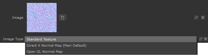
If an image is specified as a Normal Map, rotating images recalculates normal vectors for correct lighting results.
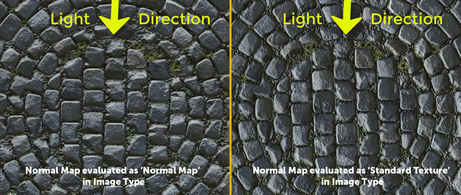
Below you can see an example of this. The Material and its normal map was rotated 90 degrees from its original output.
- With the Normal Map specified in the Image Type, Mari correctly recalculate the normal map vectors for rotation changes resulting in consistent lighting in viewport & render.
- If the Normal Map is treated as a 'Standard Texture', no normal orientation is recalcuated, resulting in incorrect lighting in viewport & render
- Image Rotation
A rotation on the 'Texture Map' in local space of the map itself
- Slide
A translation/offset on the 'Texture Map' in local space of the map itself. This is useful to slide the texture along the cylindrical projection.
- Lock UV Scale
When adjusting the 'Length' parameter of the projection the texture repeat changes by default.
With Lock UV Scale turned on adjusting texture repeat will compensate for changes in 'Length'
- Length
The Length/Height of your cylindrical projection
|
|
Changing Slider Range If you feel that your length (or any other positional value) is changing too fast even with small slider changes, go to the 'Transform Helpers' Group in the Cylindrical Projection Node and set the multiplier lower ! |
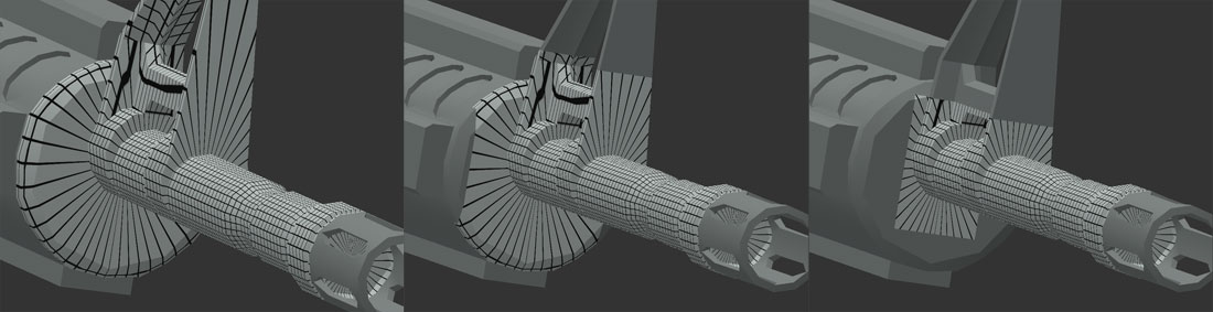
- Radius
The radius of your cylindrical projection determines where the projection will be clipped.
- Please note due to performance reasons the clipping is done square, not round.
Different Radius on a projection:
- Squash
Squashes the profile of the cylinder that is projecting. This is useful to redistribute features on objects that are not
100 % cylindrical to avoid texture stretching or deliberately introduce it.

- RepeatU
Texture Repeat around the circumference of the cylinder
- RepeatV
Texture Repeat along the length of the cylinder
- UV Scale
Uniform Texture Repeat multiplier for RepeatU and RepeatV
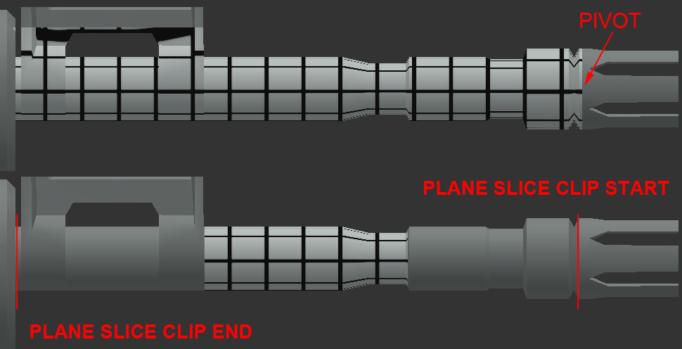
- Plane Slice Start / End
Plane Slice will cut the texture projection from either start or end of the cylinder.
The base of the cylinder (pivot) determines which side Plane Slice Start is on.
- Offset
A secondary offset on the main slider with a finer granularity on the slider for fine adjustments
- Pie Slice Start / End
Pie Slice will slice the Projection around the circumference of the cylinder
- Offset
A secondary offset on the main slider with a finer granularity on the slider for fine adjustments
|
|
These options only apply, if the supplied input image is set to a normal map |
- Invert Red
Will invert the Red Channel of the attached Normal Map
- Invert Green
Will invert the Green Channel of the attached Normal Map
|
|
OpenGl vs DirectX Normal Map Mari's Shaders by default expect a Direct X Normal Map. If you have an OpenGl Normal Map you will have to invert the Green Channel to get a Direct X Normal Map |
- Switch Red/Green
Allows you to swap the Red/Green Component of a Tangent Space Normal Map attached to the Node in the
Nodegraph
- Mirror X / Mirror Y
Will mirror the vectors of the normal map. This is useful to align the Normal Map correctly in space for your projection
EXTRA ATTRIBUTES TAB
|
|
Extra Attributes vs. Locators Please note the options below are working on top of any locators created via the Interactive Placement tab, meaning that by modifying the extra attributes the locator position will no longer be 100% representative of your cylinder pivot position |
- Display Object Position as Color Value
Shows your objects position values (X,Y,Z) as RGB Values so they can be sampled with the Pixel Analyzer Tool.
Refer to How to position your Projection in 3D Space for more details.
- X / Y / Z Offset
The X, Y and Z Position of your Cylinder Pivot relative to its original position (world 0 or locator position). These values can be obtained by sampling the position with the Pixel Analyzer Tool
- Offset
A secondary offset on each main slider with a finer granularity on the slider for precision positioning
- Rotate X / Y / Z
Rotates the cylinder around the pivot of the projection.
- Offset
A secondary rotation offset on each main slider with a finer granularity on the slider
Depending on your scene size some of the default slider ranges might be too large.
The following multipliers will help you compensate for very large or very small object sizes.
- Global Multiplier
A multiplier on Length+Radius, the fine Offset Controls of Cylinder Pivot & Rotate Cylinder (not the main sliders !)
as well as the the fine Offset Controls on the Clipping Options (not the main sliders).
If any of the sliders below are used, the result will be multiplied.
- Length/Radius Multiplier
A multiplier on Length & Radius Controls.
- Transform Offset Multiplier
A multiplier on the fine offset controls of Cylinder Pivot & Rotate Cylinder (not the main Offset sliders ! )
- Clip Offset Multiplier
A multiplier on the fine offset controls of Projection Clipping Options (not the main Clip sliders ! )
INTERACTIVE PLACEMENT TAB
- Projection Pivot
Allows you to specify a locator to use for interactive translation of the projection in the viewport.
Please refer to How to Position the Projection in 3D Space for more detailed information.
In addition to the translation options here you can fine tune the position using the attributes under the
'Extra Attributes (Pivot Translation)' Group
- Mirror
Sometimes after positioning your cylinder pivot, the cylinder might be 'standing on the pivot' facing the wrong direction.
Instead of rotating the cylinder again, simply tick or untick Mirror to tip the cylinder on its head.
- Projection Rotation
Allows you to specify a locator to use for interactive rotation of the projection in the viewport
Please refer to How to Position the Projection in 3D Space for more detailed information
In addition to the rotation options here you can fine tune the position using the attributes under the
'Extra Attributes (Pivot Rotation)' Group