|
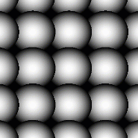
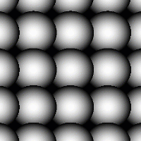
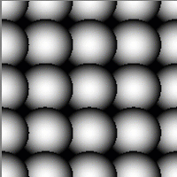
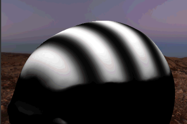
Symmetry Pattern X1 Triplanar |
- Where to find it:
- Add Procedural Layer / Procedural / Extension Pack / Generators
 NodeGraph / Right Mouse Click / Add Nodes / Procedurals / Extension Pack / Generators
|
|
This Node is also available as a 2D Version |
Modifications of the Pattern Generator Nodes, Symmetry Pattern Nodes are specifically optimized for
symmetrical patterns
|
|
It is recommended to cache this node or attach a bake point after you are done tweaking it to keep its performance impact low |
This Node shares Attributes with the Main Pattern Generator Nodes.
An in-depth tutorial on every feature of the Pattern Generator Nodes can be found below:
Pattern Engine Overview
This Node is part of a collection of Nodes making up the Pattern Engine:
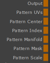
- Output
The Default Output
- Pattern UVs
Outputs the UV coordinates of the cells
- Pattern Center
Outputs the center UV coordinate for each cell as a uniform value across the entire cell
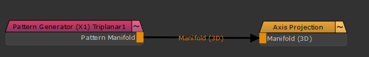
- Pattern Manifold
Outputs Manifold Data from the node that can be used to drive other nodes.
A simple example of a Pattern Generator Node driving another node via the Manifold Output
- Pattern Index
Outputs a R,G,B packed Index
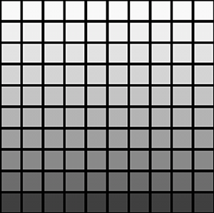
- R - Row Index
Multiplies the normalized Row Number (0.0 - 1.0) against the result.
Each row will have a different value this way
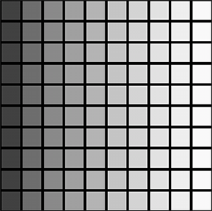
- G - Column Index
Multiplies the normalized Column Number (0.0 - 1.0) against the result
Each column will have a different value this way
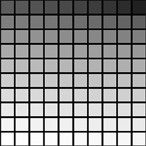
- B - Pattern Index
Multiplies the normalized Cell Number (0.0 - 1.0) against the result
Each cell will have a different value this way
- Pattern Scale
Change the Value of each Cell based on the Cell scale.
Evaluated are Random Size X/Y, Random Scale,Random Scale Map, Normal Map
Example of Scale Output
- Pattern Mask
Outputs the pure pattern result as a mask without the Background Color applied
- Pattern Random
Outputs the random signal used inside the node to randomize elements
- Pattern Specific 1
An option to change the look of the generated Pattern. Varies based on Patttern. Overwrites Pattern Specific 1 Slider if mapped,.
- Pattern Specific 2
An option to change the look of the generated Pattern. Varies based on Patttern. Overwrites Pattern Specific 2 Slider if mapped,.
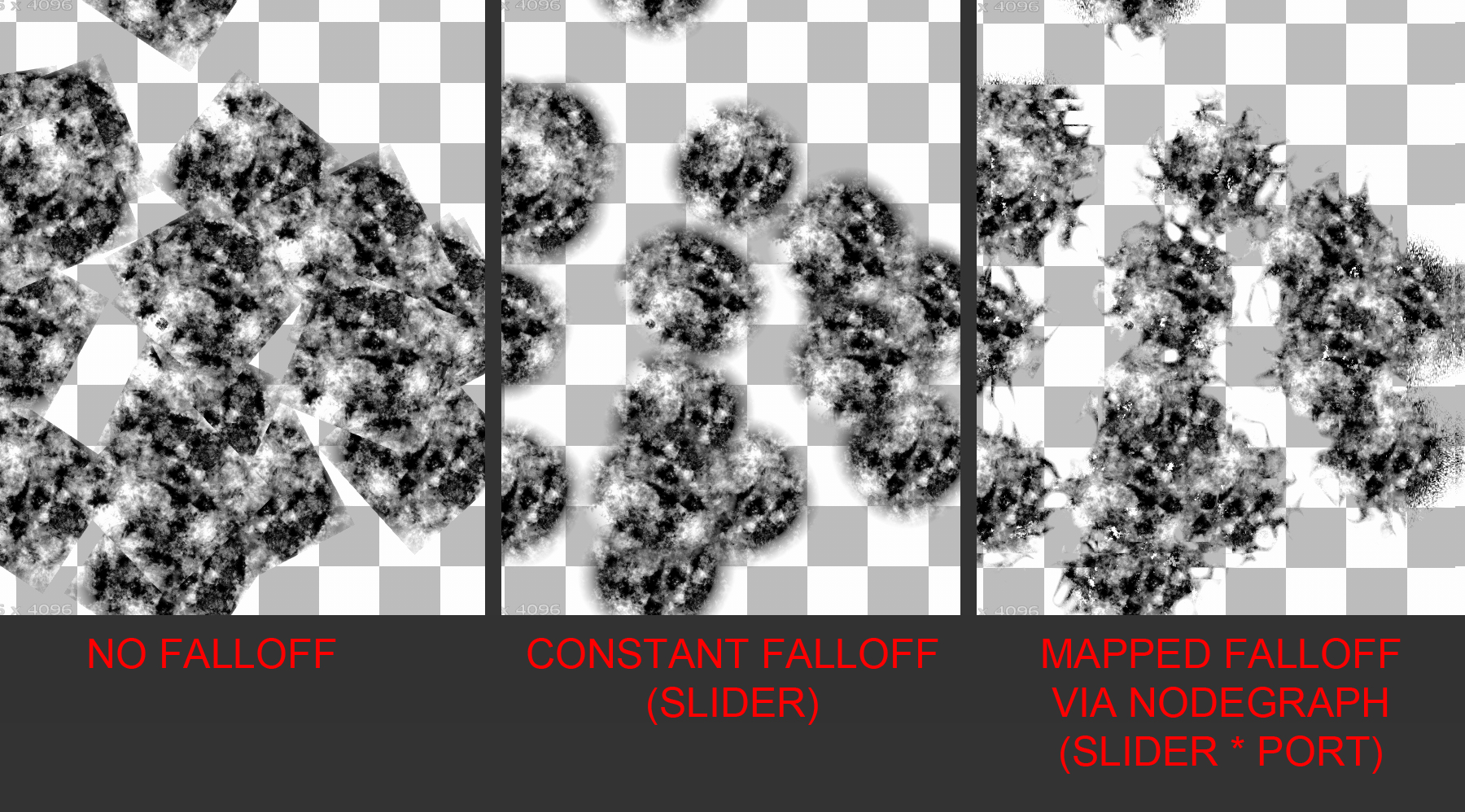
- Edge Falloff
An option to change the look of the generated Pattern. Varies based on Patttern. Overwrites Pattern Specific 2 Slider if mapped,.
- Edge Falloff
Allows you to overwrite the Edge Falloff Attribute in the Pattern Group
- Edge Softness
Allows you to overwrite the Edge Softness Attribute with a Node Connection
- Edge Roundness
Allows you to overwrite the Edge Roundness Attribute with a Node Connection
|
|
Any value fed in through the Edge Ports on the Node is still multiplied against the corresponding Edge Slider in the Texture Groups of the Node. |
- Amount
Allows setting the Amount of Cells via a Nodegraph Input.
Will overwrite the Amount X and Amount Y Sliders.
Separate values can be fed to X and Y by specifying different values for Red and Green channel of the attached node stream
Allows for scale changes to Cell contents. Gets multiplied against the Scale & Size Settings found in the Size Group
|
|
Scale Maps are evaluated per Pixel, not per Cell. |
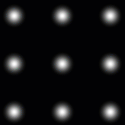
Example of a cloud node
attached to the scale map port
Allows for setting a Pattern Background. Fill Background needs to be turned on
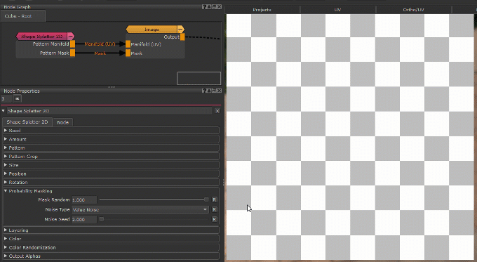
- Bake Point Image
![]()
The Bake Point Image Port allows you to feed data into the Node from upstream nodes that have been baked via a bake point into the Node.
When the node is evaluated, the Bake Point attached to the Port will be sampled and the UDIM 1001 Image will be transferred into
the Image Attribute of the Node.
This allows you to create patterns and textures via a nodegraph and use them directly inside this node with an element of non-destructivness
Example of using a Nodegraph and a Bake Point to dynamically feed a Pattern Generator Node with Node Inputs
- Manifold 3D
When mapped the world space position the node uses to calculate the projection is supplied by the port.
This can be used for example to apply warping to the projection using Manifold Nodes
- 3D Rotation (XYZ)
When mapped the red channel of the attached connection is used to drive the Projection Rotate X Attribute,
the green channel the Projection Rotate Y Attribute and the blue channel the Projection Rotate Z Attribute
- UV Scale Right (UV)
Determines the UV Scaling of the Projection from the Right side
- UV Scale Top (UV)
Determines the UV Scaling of the Projection from the Top side
- UV Scale Front (UV)
Determines the UV Scaling of the Projection from the Front side
- UV Angle (XYZ)
When mapped the red channel of the attached connection is used to drive the UV Rotation Right Attribute,
the green channel the UV Rotation Top Attribute and the blue channel the UV Rotation Front Attribute
- UV Offset (UV)
When mapped the red channel of the attached connection is used to drive the U Offset Attribute,
the green channel the V Offset Attribute
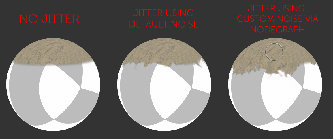
By default the Edge Blending Jitter uses a node internal noise to perform its jittering/randomization of edges.
By attaching a noise of your choosing to the Jitter Noise Connection in the Nodegraph you can overwrite this
internal noise.
MAIN TAB
- Random Seed
By modifying the Random Seed, different looks can be achieved with the otherwise same settings.
- Amount Multiplier
A multiplier on the amount of Cells generated. Each cell is processed independently with the given settings (Position, Rotation etc. etc.)
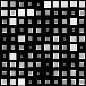
- Amount X
Amount of cells generated horizontally. Each cell is processed independently with the given settings (Position, Rotation etc. etc.)
- Amount Y
Amount of cells generated vertically. Each cell is processed independently with the given settings (Position, Rotation etc. etc.)
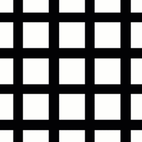
Determines what pattern is used to fill each cell.
Options are
- A File Texture (Input Image)
Supply a Texture in the Input Image Section
- One of 23 procedurally generated Patterns
For a complete overview of all procedural patterns visit the Shape Node Help
An Option to change the look of procedurally generated Patterns. Varies based on Patttern
|
|
This Setting has no effect if Input Image has been chosen under Pattern |
- Pattern Specific 2
An Option to change the look of procedurally generated Patterns. Varies based on Patttern
|
|
This Setting has no effect if Input Image has been chosen under Pattern |
Determines the size of the procedurally generated Pattern within a cell.
Please note this works together with any size/scale specified in the Size Group.
|
|
This Setting has no effect if Input Image has been chosen under Pattern |
- Pattern Rotate
Determines the rotation of the procedurally generated Pattern within a cell
|
|
This Setting has no effect if Input Image has been chosen under Pattern |
- Pattern Alpha Intensity
Determines the processing of the Alpha Channel of a procedurally generated pattern.
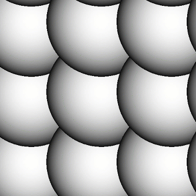
Example of reducing the Alpha Intensity from 1 to 0 on a large Hemisphere pattern
|
|
This Setting has no effect if Input Image has been chosen under Pattern |
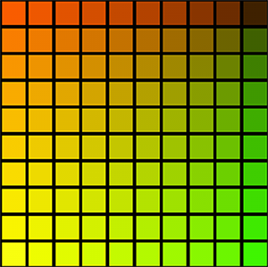
- Pattern Repeat U
Repeats the pattern or input image x-amount of times horizontally in each cell.
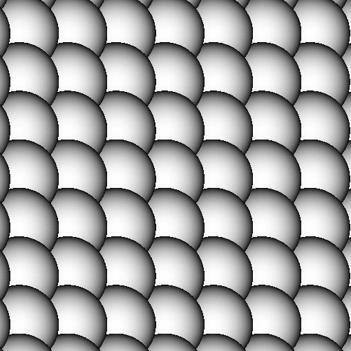
Example of increasing Pattern Repeat U
on a 'Gaussian' Pattern
- Pattern Repeat V
Repeats the pattern or input image x-amount of times vertically in each cell.
- Invert Pattern
Invert pattern or Input Image
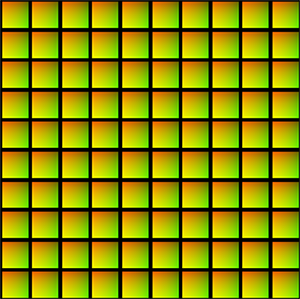
- Blend Mode
The Blend Mode used to overlay a cell over other cells
Example of different effects achieved by changing the blend mode
The Edge Controls give you control over the edge transparency of the generated pattern, allowing you to create 'Brush Effects'
- Edge Falloff
Will contract the edges of your loaded textures. This parameter can also be mapped via the Nodegraph
- Edge Softness
Will feather the edges of your loaded textures from the start of the Edge Falloff to the centre of your texture.
This parameter can also be mapped via the Nodegraph
- Edge Roundness
Switches the Falloff from Square (0.0) to Radial (1.0).
This parameter can also be mapped via the Nodegraph
- Edge Distortion
The Edge Distortion is distorting the alpha in the softened areas based on the luminance of the pattern.
If Edge Distortion is 1.0 black parts of the pattern inside the cell will be hidden in the area of Edge Softness.
If Edge Distortion is -1.0 white parts of the pattern inside the cell will be hidden in the area of Edge Softness.
Example of raising Edge Distortion from 0 to 1
The Pattern Crop options allow to 'cut' the edges of a patterns or input images, allowing even more variation
Example of using the Pattern Crop to generate a triangle from a square
- Top
Control the Crop from Top to Bottom per Shape
- Bottom
Control the Crop from Bottom to Top per Shape
- Left
Control the Crop from Left to Right per Shape
- Right
Control the Crop from Right to Left per Shape
- Rotate
Rotate the Crop 'Frame' around its center
- Map
Supply a texture map to use in the processing.
|
|
This setting is only evaluated if Pattern is set to 'Input Image' |
- Mipmap Blur
Allows you to blur the input image. This feature requires Mari 4.6v2.
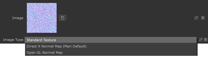
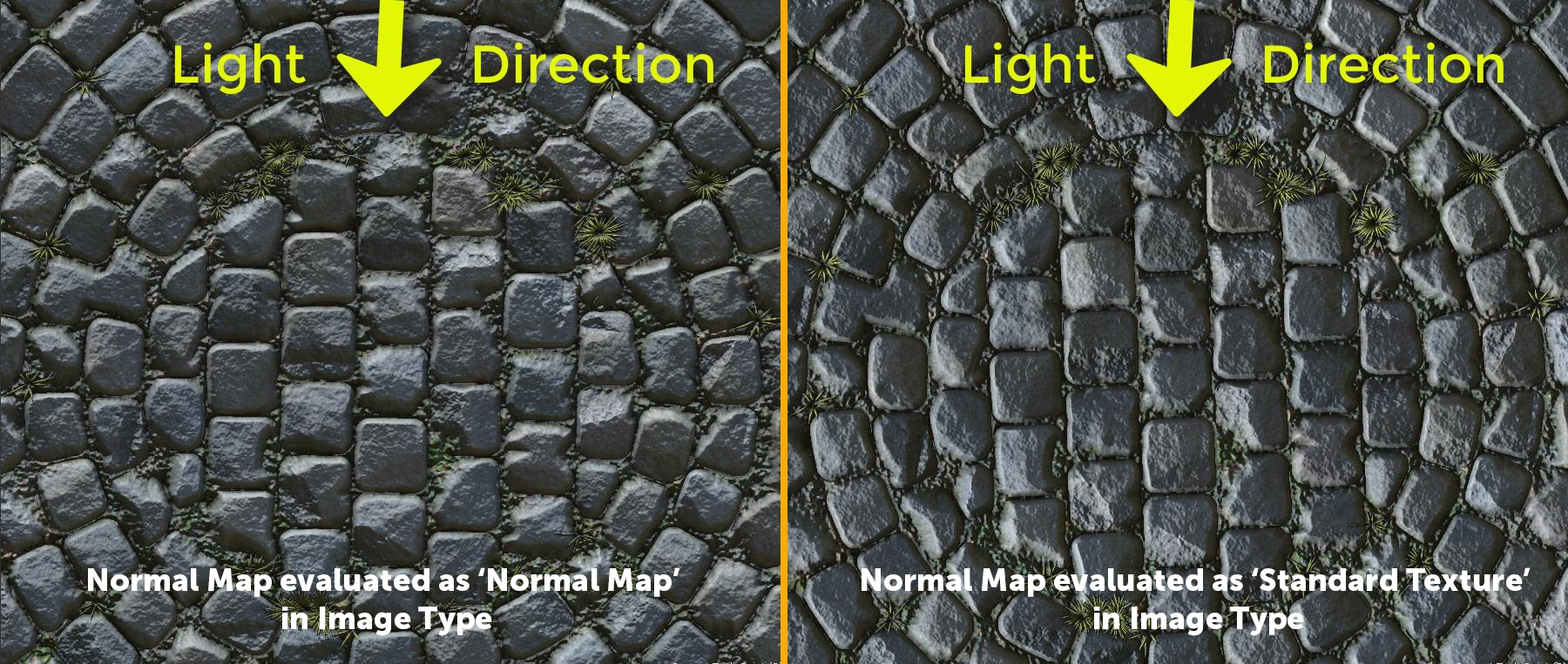
- Image Type
If an image is specified as a Normal Map, rotating images recalculates normal vectors for correct lighting results.
Below you can see an example of this. The Material and its normal map was rotated 90 degrees from its original output.
- With the Normal Map specified in the Image Type, Mari correctly recalculate the normal map vectors for rotation changes resulting in consistent lighting in viewport & render.
- If the Normal Map is treated as a 'Standard Texture', no normal orientation is recalcuated, resulting in incorrect lighting in viewport & render
- Alpha
Configure the Alpha Handling of the supplied image.
- From Map
The Transparency in your loaded texture map is used
- Alpha is Luminance
The Luminance of your loaded texture map is used as Alpha.
Black is transparent.
- Alpha is Inverted Luminance
The inverted Luminance of your loaded texture map is used as Alpha.
White is transparent.
- White
The Alpha of the loaded map is set to white resulting in the image being 100% opaque.
|
|
This setting is only evaluated if Pattern is set to 'Input Image' |
- Size X
The horizontal size of each cell
- Size Y
The vertical size of each cell
- Scale
A uniform scale factor.
|
|
If Pattern is set to a procedural pattern, scale works together with Pattern Size. Set both to 1.0 for 100% Scale |
- Random Scale
Mix Factor for uniform scale randomization.
Positive Values (0 - 1) will reduce the size of the cells randomly.
Positive Values (0 - 1) will increase the size of the cells randomly.
- Offset
Sets an offset for cells. The type of offset is determined by the Offset Type (see below)
- Offset Type
- Horizontal quuincux
Controlled by the Offset Slider this will offset every second row of cells
- Vertical quuincux
Controlled by the Offset Slider this will offset every second column of cells
- Horizontal Global Normalized
This will add the value specified in Offset to each row successively then normalize the Offset to prevent it from going over 1.0.
e.g.
Offset Value = 0.2
Row 1 will receive an offset of 0.2 in X
Row 2 will receive an offset of 0.4 in X
Row 3 will receive an offset of 0.6 in X
Row 4 will receive an offset of 0.8 in X
.
.

- Verrtical Global Normalized
This will add the value specified in Offset to each row successively then normalize the Offset to prevent it from going over 1.0.
e.g.
Offset Value = 0.2
Row 1 will receive an offset of 0.2 in X
Row 2 will receive an offset of 0.4 in X
Row 3 will receive an offset of 0.6 in X
Row 4 will receive an offset of 0.8 in X
Row 5 will receive an offset of 1.0 in X
Row 6 will receive an offset of 0.2 in X
Row 7 will receive an offset of 0.4 in X
.
.
- Horizontal Global
This will add the value specified in Offset to each row successively.
e.g.
Offset Value = 0.2
Row 1 will receive an offset of 0.2 in X
Row 2 will receive an offset of 0.4 in X
Row 3 will receive an offset of 0.6 in X
Row 4 will receive an offset of 0.8 in X
Row 5 will receive an offset of 1.0 in X
Row 6 will receive an offset of 1.2 in X
Row 7 will receive an offset of 1.4 in X
.
.
|
|
Higher Horizontal Global Values will require a higher Layer Cutoff Value, which in turn reduces performance. However if not raised you will notice pattern disappearing once the layer cutoff is reached. Consider using the Vertical Global Normalized mode instead which can achieve the same effect with lower Values |
- Vertical Global
This will add the value specified in Offset to each column successively.
e.g.
Offset Value = 0.2
Column 1 will receive an offset of 0.2 in Y
Column 2 will receive an offset of 0.4 in Y
Column 3 will receive an offset of 0.6 in Y
Column 4 will receive an offset of 0.8 in Y
Column 5 will receive an offset of 1.0 in Y
Column 6 will receive an offset of 1.2 in Y
Column 7 will receive an offset of 1.4 in Y
.
.
|
|
Higher Horizontal Global Values will require a higher Layer Cutoff Value, which in turn reduces performance. However if not raised you will notice pattern disappearing once the layer cutoff is reached. Consider using the Vertical Global Normalized mode instead which can achieve the same effect with lower Values |
- Global Offset X/Y
Applies a global offset of the generated Pattern (all cells) along X or Y
- Rotation
Applies a rotation to each cell
- Global Rotation
Rotates the end result of the Pattern Generation. (globally, instead of per cell)
- Alternate Rotation
Applies a secondary rotation to the cells specified in the Alternate Rotation Method
Example of an alternate Rotation
with the Alternate Rotation Method set
to "Every Second row"
- Alternate Rotation Method
Determines which cells are affected by the Alternate Rotation Slider.
- Every Second Row
- Every Second Column
- Every Second Row and Column
- Rotation Random
Applies a random rotation to Cells
- Alternate Symmetry
Applies a Mirroring effect to the cells specified
- None
Alternate Symmetry is disabled (default)
- Every Second Row
Every second row is mirrored in X, Y or X and Y (depending on the setting chosen in Alternate Symmetry affects)
- Every Second Column
Every second column is mirrored in X, Y or X and Y (depending on the setting chosen in Alternate Symmetry affects)
- Every Second Row and Column
Every second Row and column is mirrored in X, Y or X and Y (depending on the setting chosen in Alternate Symmetry affects)
- Mirrored
Similar to Every Second Column tries to create mirrored pairs in X.
Ignores Alternate Symmetry affects.
- Alternate Symmetry affects
Determines the mirroring axis for the Alternate Symmetry.
|
|
This setting is not evaluated if Alternate Symmetry is set to Mirrored. |
- Random Symmetry
Applies a Mirroring effect to random selection of cells
Example of Random Symmetry in X

- Random Symmetry affects
Determines the Mirror Axis to use for Random Symmetry
- Flip X / Y
Flips the cells in X or Y
- Alternate Masking
Applies a alternate Masking to the cells specified
- Ignore
Alternate Masking is disabled (default)
- Every Second Row
Every second row is hidden
- Every Second Column
Every second column is hidden
- Every Second Row and Column
Every second Row and column is hidden
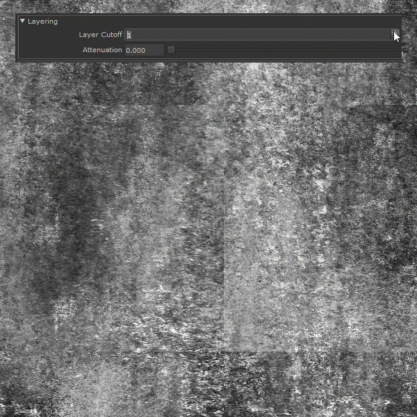
- Layer Cutoff
The Layer Cutoff determines the number of iterations and radius around each cell the node runs through before it stops calculating.
If you are experiencing Seams this might be the reason
|
|
Higher Layer Cutoff Values reduces performance ! Keep this value as low as possible without seeing seams |
To better understand this behavior and to anticipate consider this:
- By default each cell is generated in a grid pattern at a scale of 1.
- Each cell has an internal position of 0.0 for its own coordinate system
If you change the position of a cell from its original position of 0.0/0.0 the Layer Cutoff needs to be increased
for a wider sample radius. So for example
- adding a Random Position Value of 1.0/1.0 means we need to sample up to 1 additional cell around the original cell.
- We need to increase the Layer Cutoff to at least 2
- adding a Random Position Value of 2.0/2.0 means we need to sample up to 2 additional cell around the original cell.
- We need to increase the Layer Cutoff to at least 3
If you change the scale of a cell from its original scale of 1.0 the Layer Cutoff needs to be increased
for a wider sample radius. So for example
- Changing the Scale to 2 means we need to sample 1 additional cell around the original cell.
- We need to increase the Layer Cutoff to at least 2
- Changing the Scale to 4 means we need to sample 3 additional cell around the original cell.
- We need to increase the Layer Cutoff to at least 4
If ticked on, the Pattern will be generated over the Background defined in the Background Color or the background attached to the Background Node port
- Background Color
The Background Color for the Pattern if Fill Background is ticked on. The Background Color is ignores if something is attached to the Background Node port
- Scale Normal Map Intensity
If a Normal Map is used in the Input Image, this slider can be used to modulate the normal strength based on the size of the feature
|
Output Alphas |
The Settings found in the Output Alphas Group determine how transparency of cell content is treated in the additional Output Ports of the Node
(Pattern UVs, Pattern Center, Pattern Index, Pattern Manifold and Pattern Scale)
- UVs premultiply
Premultiplies the transparency of cell content returned on the Pattern UVs output Port
- Center premultiply
Premultiplies the transparency of cell content returned on the Pattern Center output Port
- Index/Manifold premultiply
Premultiplies the transparency of cell content returned on the Pattern Index and Pattern Manifold output Ports
- Scale premultiply
Premultiplies the transparency of cell content returned on the Pattern Scale output Port
|
|
These options only apply, if the supplied input image is set to a normal map |
- Mirror X Front / Mirror Y Front
Will mirror the vectors of the normal map for the Front Projection Direction. This is useful to align the Normal Map correctly in space for your projection
- Mirror X Top / Mirror Y Top
Will mirror the vectors of the normal map for the Top Projection Direction. This is useful to align the Normal Map correctly in space for your projection
- Mirror X Right / Mirror Y Right
Will mirror the vectors of the normal map for the Right Projection Direction. This is useful to align the Normal Map correctly in space for your projection
TRANSFORM TAB
|
Triplanar Settings |
The Triplanar Settings control the projection of the texture in 3d space.
The settings are similar to a regular Triplanar Node found in Mari.
- Manifold World Scale
The Manifold World Scale controls the size of the Manifold Coordinates returned by the Pattern Manifold Output Port of the Node.
It only affects this Output Port.
|
|
Due to the nature of the node, this Triplanar Projection Node does not have a WorldScale Option to scale the overall size of the features. Use The Amount Settings in the Main Tab to change the Size |
An example of using the Manifold World Scale would be when the node is connected to e.g. an Axis Projection via the Pattern Manifold -> Manifold 3D
connected to drive the look of the Axis Projection by the Pattern Engine Node.
The size of the projection of the Axis Projection in this case would be controlled by the Manifold World Scale of the Pattern Engine Node.
Example of driving an Axis Projection Node via the Pattern Manifold of the Pattern Engine Node.
- Projection Rotate X/Y/Z
Will change the rotation of the Triplanar 'Projection Cube' in space.
This should not be confused with changing UV Rotation which will rotate the projected image on
each side of the projection.
Projection Rotate is useful if your asset is not perfectly aligned in the main world space axis X Y and Z
and you see projection stretching as a result of it.
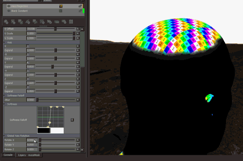
Sample of rotating a projection in 3d space. While this example is using
an Axis Projection Node the concept is the same for the Texture Scatter Triplanar Node
- Edge Falloff Start
The Edge Falloff Start determines the minimum angle where the projection
starts to be fully opaque
- Edge Falloff End
The Edge Falloff End determines the maximum angle where the projection
starts to be fully transparent
- Edge Falloff
The Edge Falloff Curve determines the general Falloff of each projection axis to its sides.
This is similar to adjusting the Edge Falloff Start and Edge Falloff End Sliders however
it allows you to create non-linear edge blending
Jitter will make the edges of projections less uniform/straight.
The Jitter Intensity determines the amplitude of the the Jitter.
You can overwrite the Noise used for jittering the edges by mapping the Jitter Noise Port in the Nodegraph
- Jitter Scale
Determines the Frequency of the internal Noise used for jittering.
|
|
Jitter Scale is ignored if something is attached via the Nodegraph to the Jitter Noise Port |
|
UV Settings |
- Scale Right
Changes the UV Scale of the Right Side Projection
- U Scale Right
Will scale the UVs for the Right Side Projection along U (Horizontally)
- V Scale Right
Will scale the UVs for the Right Side Projection along U (Vertically)
- Scale Top
Changes the UV Scale of the Top Side Projection
- U Scale Top
Will scale the UVs for the Top Side Projection along U (Horizontally)
- V Scale Top
Will scale the UVs for the Top Side Projection along U (Vertically)
- Scale Front
Changes the UV Scale of the Front Side Projection
- U Scale Front
Will scale the UVs for the Front Side Projection along U (Horizontally)
- V Scale Front
Will scale the UVs for the Front Side Projection along U (Vertically)
Will rotate the result for all axis of the Triplanar Projection
- UV Rotation Right
Will rotate the UVs just along the X-Axis of the Triplanar Projection.
- UV Rotation Top
Will rotate the UVs just along the Y-Axis of the Triplanar Projection.
- UV Rotation Front
Will rotate the UVs just along the Z-Axis of the Triplanar Projection.
- U Offset
Will offset the result along U.
- V Offset
Will offset the result along V.
|
Texture Seams ? |
If you are seeing seams in your pattern try raising the Layer Cutoff
|
|
Higher Layer Cutoff Values reduces performance ! Keep this value as low as possible without seeing seams |